
Blog
What's New in Autodesk Civil 3D 2025?
Our Consultant, Enrique Barriuso, provides an overview of the new features, improvements, and updates in Autodesk Civil 3D 2025.

WHAT’S NEW FOR INVENTOR 2017.3
Inventor 2017.3, is an update for customers on subscription, delivers fixes and over 20 product enhancements in projected sketch references, intelligent interference filtering and 3D PDF publishing. This update also provides the next step in product learning with a unified learning experience that enables customers to create, manage and publish learning content.
Measure Enhancements


Additional Workflow Enhancement
You can now use a crossing window to select multiple closed profiles when creating features with the Revolve, Sweep, Coil, Chamfer, and Fillet commands.
3D PDF
3D PDF export is significantly faster and now supports View representation color overrides.

Select Tangencies Now Available within Project Geometry Command
The Select Tangencies behaviour, previously only available in Parts and Assemblies, is now also available in the sketch environment when the Project Geometry command is active. You can now quickly create a selection set of all the faces or edges tangent to each other in the sketch Project Geometry:
OR
Projected Sketch References are Now Maintained After Redefining a Sketch
Previously if you redefined the plane that a part or assembly sketch was created on, the projected references were lost (sketch turned green) whereas now if you redefine the sketch plane, the associativity is maintained (sketch remains yellow). This applies to the following types of sketch references:
New Options in Application Options  Sketch tab Enhance Performance
There are now separate settings for controlling the Look at behaviour in an assembly sketch and controlling the Look at behaviour in a part sketch in the Applications Option dialog box Sketch tab.
Now that there are separate settings for part sketch and assembly sketch, you can, for example, disable looking at the sketch plane when editing a component and have Look at enabled when editing an Assembly sketch.

The setting In Part Environment controls Look at behaviour:
The setting In Assembly Environment controls Look at behaviour when creating or editing an assembly sketch.
New 3D Sketch Mini-Toolbar and 2D Sketch Mini-Toolbar Options
A mini-toolbar is added to the 3D sketch environment.
 Edit 3D Sketch: Displays when selecting a 3D sketch in the part and sheet metal environment.
Additionally, the following options are added to the new 3D sketch mini-toolbar and to the existing 2D sketch mini-toolbar. The following options display when selecting a 2D or 3D sketch based feature:
 Share Sketch: Displays in the part and sheet metal environment and the sketch is not shared.
 Unshare Sketch: Displays in the part and sheet metal environment and the sketch is shared.
 Make visible: Displays in all part and assembly environments and visibility is off.
 Make invisible: Displays in all part and assembly environments and visibility is on.
Convert Sketch Text to Geometry
You can now convert part, assembly, and drawing sketch text into sketch geometry (lines, arcs). Use converted text geometry to create text engravings, for example, to laser etch part numbers or stock information onto models.
After the text is converted to standard sketch geometry, the converted geometry is no longer associative with the original text.
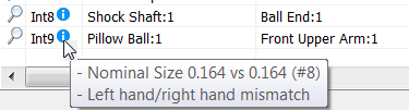
Multiple Enhancements to Analyze Interference

.


Mismatched threads display the interference type in a tooltip for 4 interference types.
 a thread interference value into Excel.

Assembly Shrinkwrap Options Dialog Box Enhancement
The setting, Use color override from source component, is now available in the Assembly Shrinkwrap Options Dialog Box. Use this option to link color from the base component into the target part. If unchecked, the appearance is set to the default appearance of the target part.
Create and Share Tutorials
You can now create your own tutorials and share them publicly or privately. This enhancement adds two new categories to Type. Click My Tutorials to display and manage tutorials you create. Click Shared With Me to display tutorials that are shared privately with you.

When you click Create Tutorial to start the authoring process, the Anatomy of a Tutorial visual guide is displayed. Click the How to links on the Anatomy page to watch two short videos that guide you through the create and share process.

A new workflow is provided for preparing Inventor models for use as BIM Content via Configurator 360.

